GSR Type 40 Solenoid Valve – Automatic Flow Control Solution for Industrial Systems
19/08/2026In industrial piping systems, accurately controlling the supply, shut-off, or distribution of media is an important requirement to ensure stable and safe system operation. In addition to manually operated valves, solenoid valves are widely used thanks to their ability to automatically open and close through electrical signals, ease of integration with control and automation systems.
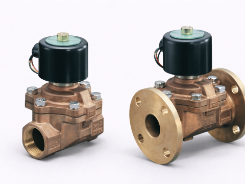
GSR Ventiltechnik is a brand specializing in industrial valve solutions, including the Baureihe 40 / Type 40 series, a 2/2-way solenoid valve designed for various types of media and applications. This valve series uses a diaphragm design, operates according to the pilot principle, and has a standard normally closed (NC) configuration.
With various options for connection sizes, valve body materials, coil voltages, and configuration options, the GSR Type 40 solenoid valve can meet many requirements in water, gas, liquid, and industrial automation systems.
1. What is the GSR Type 40 Solenoid Valve?
The GSR Type 40 is a 2/2-way solenoid valve from GSR Ventiltechnik, used to control the opening and closing of media flow by means of an electrical signal.
The designation 2/2-way indicates that the valve has:
- 2 connection ports;
- 2 operating positions.
The version shown in the technical documentation is normally closed – NC, meaning that when the coil is not energized, the valve remains closed.
When the solenoid coil is energized, the internal magnetic mechanism is activated. The pressure on the secondary side of the diaphragm is decompressed through the pilot hole, allowing the differential pressure to act on the diaphragm and lift the piston from the valve seat. The valve then opens and allows the medium to flow through.
An important point of the Type 40 series is that the minimum specified differential pressure shown in the specification table must always be maintained for the valve to operate correctly. This is an important factor to consider when selecting the valve for a system.
2. Operating Principle of the GSR Type 40 Solenoid Valve
The GSR Type 40 uses a pilot-operated diaphragm design.
Its operating principle can be understood through two main states.
2.1. When the Valve is Not Energized
Under normal conditions, the valve is closed (NC).
The coil is not energized, so the solenoid does not generate a force to lift the piston. The diaphragm remains in the closed position and prevents the medium from passing through the valve port.
This configuration allows the system to maintain the closed condition when electrical power is lost or when the control signal has not yet been activated.
2.2. When the Coil is Energized
When the coil is energized, the solenoid generates a force acting on the piston.
Through the pilot mechanism, the pressure on the secondary side of the diaphragm is released through the pilot hole.
The pressure change creates a differential pressure acting on the diaphragm. When the appropriate differential pressure condition is reached, the diaphragm is lifted and the piston moves away from the valve seat.
The valve then opens and the medium can flow through.
Because the valve uses the pilot principle, the minimum differential pressure is an important specification. If the system pressure does not meet the required minimum condition, the valve may not operate correctly.
2.3. When the Power is Switched Off
When the electrical signal is switched off, the magnetic force of the coil disappears. The internal mechanism returns to its initial position, the diaphragm closes, and the valve returns to the Normally Closed condition.
The operating cycle can be simply described as:
No power → Valve closed → Power supplied → Pilot activated → Diaphragm lifted → Valve open → Power switched off → Valve closed.
This operating principle is suitable for many systems requiring automatic control of media flow by electrical signals.
3. Construction of the GSR Type 40 Solenoid Valve
The GSR Type 40 solenoid valve consists of several components that work together to perform the flow control function.
According to the sectional drawing and parts list in the technical documentation, the main components include valve body, bonnet, diaphragm, spring, sealing plug, O-ring, piston, cylinder head, strainer, solenoid tube, solenoid plunger, solenoid, corrugated disk, seal, and other related components.
3.1. Valve Body
The valve body is the main component in contact with the medium and contains the flow passage.
GSR provides the Type 40 with different valve body material options, including:
- Brass
- Stainless steel 1.4581 / AISI 316 Ti
Material selection should be based on the type of medium, temperature, pressure, and corrosion resistance requirements of the system.
3.2. Diaphragm
The diaphragm is one of the most important components of the valve.
It participates in the opening and closing process while also ensuring that the medium is controlled inside the valve body.
The diaphragm design allows the Type 40 to operate according to the pilot principle, in which the pressure change above the diaphragm plays an important role in the valve operating process.
3.3. Piston and Spring
The piston and spring assembly works together with the pilot system and solenoid to control the opening and closing state.
When the coil is energized, the piston is actuated and the pilot process begins.
When the power is switched off, the mechanism returns to its initial position and the valve closes.
3.4. Solenoid Assembly
The solenoid assembly includes components such as:
- Solenoid tube;
- Solenoid plunger;
- Solenoid;
- Related components.
This is the component that converts the electrical signal into mechanical movement to control the valve.
3.5. Sealing Components
The Type 40 uses NBR as the sealing material according to the information in the technical documentation.
In addition to ensuring tightness, the sealing material must be compatible with the actual medium to prevent aging, swelling, or deterioration of performance.
4. Key Features of the GSR Type 40 Solenoid Valve
4.1. Normally Closed 2/2-Way Design
The normally closed design allows the system to maintain the closed condition when there is no control signal.
This configuration is suitable for applications where the medium is only allowed to flow when the system supplies an electrical control signal.
4.2. Pilot Operation
The pilot-operated design allows the valve to use the pressure difference of the medium to assist the opening and closing process.
However, because this principle is used, the user must check the operating pressure and minimum differential pressure before selecting the valve.
4.3. Multiple Material Options
Depending on application requirements, the valve body can be selected in Brass or Stainless Steel 1.4581 / AISI 316 Ti.
This allows the Type 40 to adapt to different operating conditions and material requirements.
4.4. Coil Position Adjustable by 90°
The technical documentation indicates that the coil can be changed by 90°.
This feature provides greater flexibility when installing the valve in space-limited areas.
4.5. IP65 Protection Class
The product coil has an IP65 protection class according to DIN 40050.
This is an important specification to consider when the valve is used in industrial environments exposed to dust or moisture.
4.6. 100% Duty Factor
The documentation specifies a 100% ED duty factor, indicating that the coil is designed for continuous operation according to the manufacturer’s specifications.
This is suitable for systems where the valve needs to remain in the controlled state for extended periods.
5. Technical Specifications of the GSR Type 40 Solenoid Valve
Based on the GSR catalogue, the main specifications of the Type 40 are as follows:
| Specification | Characteristics |
|---|---|
| Valve type | 2/2-way solenoid valve |
| Standard position | Normally closed – NC |
| Control type | Pilot operated |
| Design | Diaphragm design |
| Connection | G1/4″ – G2″ |
| Pressure | 0.3–20 bar depending on model |
| Medium | Neutral, gaseous and liquid media |
| Viscosity | 22 mm²/s according to documentation |
| Medium temperature | -10 to +80°C |
| Ambient temperature | +35°C |
| Valve body material | Brass / Stainless steel 1.4581 |
| Sealing material | NBR |
| Voltage | AC / DC depending on configuration |
| Protection class | IP65 |
| Duty factor | 100% ED |
Specific specifications may vary depending on the model, connection size, material, and coil configuration. Therefore, the correct product code should be checked before selecting the valve rather than relying only on the general specifications.
6. Versions and Models of the GSR Type 40
The Type 40 series is divided into various models to meet different pipe sizes and flow requirements.
The model numbers shown in the catalogue table include: D4021; D4022; D4023; D4024; D4025; D4026; D4027; D4028
The models are divided according to connection size and orifice size.
In the specification table, connection sizes range from G1/4″ to G2″, while the orifice size varies depending on the model.
This is an important factor when selecting the valve because the pipe connection size is not the only factor determining the flow capacity of the valve.
Brass Valve Body Version
Some Type 40 models use a Brass valve body.
This is a common option for systems using media compatible with brass and that do not require the corrosion resistance level provided by stainless steel.
Stainless Steel Version
GSR also provides versions using Stainless Steel 1.4581 / AISI 316 Ti.
This version can be considered for applications with higher material requirements and corrosion resistance requirements.
The selection between Brass and Stainless Steel should be based on the chemical properties of the medium as well as the actual operating conditions.
7. Options for the GSR Type 40 Solenoid Valve
One notable feature of the Type 40 series is the availability of various optional configurations.
Manual Operation – HA
HA is an option that allows the valve to be operated manually.
This function can be useful during inspection, operation, or maintenance when manual actuation is required.
Adjustable Closing Damping – SR
SR is a device that allows the valve closing speed to be adjusted.
According to the documentation:
- turning the screw to the right → valve closes more slowly;
- turning the screw to the left → valve closes faster.
This option can be used when the valve closing characteristics need to be controlled within the system.
Free of Oil and Grease – OF
The OF version is designed to be free of oil and grease.
This option should be considered for applications with special cleanliness requirements.
Free of Non-Ferrous Metal – BF
The BF option is a version without non-ferrous metals according to the configuration specified by the manufacturer.
High-Temperature Design – TM
The TM option is designed for higher-temperature environments, with the documentation indicating a design for temperatures up to +130°C.
When selecting this version, the temperature limits of the complete valve configuration should be checked rather than considering only the valve body.
Position Indicator – EH
The EH – Position Indicator option allows the valve position to be monitored through a Reed contact according to the configuration provided by the manufacturer.
This function is useful when the valve needs to be integrated into a monitoring or control system.
Explosion-Proof – Ex
GSR also provides an Ex option with different explosion-protection configurations according to the documentation.
This option is intended for environments with specific requirements for electrical equipment and hazardous areas.
The Ex version must be selected based on the hazardous-area classification, certification requirements, and actual conditions of the installation.
8. Selection Guide for the GSR Type 40 Solenoid Valve
To select the correct valve, the pipe size alone should not be used as the selection criterion.
8.1. Determine the Connection Size
The Type 40 is available in several connection sizes from G1/4″ to G2″.
The pipe size and thread connection type should be determined before selecting the valve.
8.2. Determine the Required Flow Rate
The actual system flow rate should be compared with the flow rate specification of each model.
Two valves with the same connection size do not necessarily have the same flow capacity.
Therefore, the selection should be based on flow rate and orifice rather than only on the nominal pipe size.
8.3. Check the Pressure
This is one of the most important specifications.
The Type 40 catalogue indicates a pressure range of 0.3 to 20 bar depending on the model and configuration.
In particular, because the valve operates according to the pilot principle, the required minimum pressure differential must be ensured for the opening process.
If the system pressure is lower than the required level, the valve may not open or close correctly.
8.4. Check the Temperature
The catalogue specifies a standard medium temperature range of:
-10 to +80°C
while the ambient temperature is specified as:
+35°C.
If the system operates at a higher temperature, an appropriate configuration should be considered, such as the TM option according to the manufacturer’s specifications.
8.5. Select the Material
Depending on the medium and operating environment, the following options can be considered:
Brass
or
Stainless Steel 1.4581 / AISI 316 Ti.
For corrosive media or applications with high material requirements, compatibility should be checked before selecting the valve.
8.6. Determine the Coil Voltage
The catalogue provides AC and DC coil voltage options, including configurations such as:
- AC 24 V;
- AC 110 V;
- AC 230 V;
- DC 24 V;
- and other configurations depending on the model.
Therefore, the actual control voltage of the system must be checked before ordering.
9. Applications of the GSR Type 40 Solenoid Valve
With a design intended for neutral, gaseous and liquid media, the GSR Type 40 can be used in various flow-control systems.
Some application groups include:
Water Systems
The valve can be used to automatically open and close water flow in water supply systems and equipment control systems.
Gas Systems
The Type 40 can be used in systems utilizing gaseous media that are compatible with the valve materials.
Automation Systems
The solenoid valve can receive signals from:
- PLCs;
- controllers;
- relays;
- sensors;
- automation systems.
The valve can then perform automatic opening and closing of the medium flow according to operating conditions.
Media Treatment and Distribution Systems
The valve can be installed at piping branches to perform automatic flow opening and closing functions during production processes.
However, confirming suitability for a specific chemical or medium requires consideration of actual material compatibility and should not be based only on the name of the medium group.
10. Installation and Operation Considerations
Check the Flow Direction
Before installation, the correct flow direction should be identified according to the marking on the valve body.
Installing the valve in the wrong flow direction may affect its operation.
Ensure the Differential Pressure Condition
Because the Type 40 uses the pilot operating principle, pressure conditions are an important factor.
The pressure and differential pressure must be within the required range of the selected model.
Check the Coil Installation Position
The catalogue allows the coil position to be changed by 90°, providing greater flexibility in installation.
However, the installation position should still ensure convenient access for:
- electrical connection;
- inspection;
- maintenance;
- coil replacement when required.
Check the Power Supply
Before energizing the valve, the following should be confirmed:
- voltage;
- AC/DC;
- power consumption;
- wiring diagram.
Applying an incorrect voltage may damage the coil or prevent the valve from operating.
Check the Medium
The medium must be compatible with the materials of:
- valve body;
- diaphragm;
- sealing;
- components in contact with the medium.
Especially for chemical media, compatibility should be checked before the valve is put into operation.
Clean the Piping System
Contaminants from the piping system may affect internal valve components, particularly the diaphragm, pilot hole, and moving components.
Therefore, the piping system should be cleaned before the valve is put into operation.
Protecting the valve from contaminants also helps reduce the risk of incomplete closing or unstable operation.
11. Why Choose the GSR Type 40 Solenoid Valve?
GSR Ventiltechnik provides the Type 40 series with various options to meet different system requirements.
Some notable features include:
Normally Closed 2/2-Way Design
Suitable for systems requiring flow control through electrical signals and requiring the valve to return to the closed position when the signal is lost.
Multiple Sizes
The connection range from G1/4″ to G2″ makes it possible to select the appropriate valve according to the pipe system size.
Multiple Material Options
Brass and Stainless Steel 1.4581/AISI 316 Ti allow users to select the configuration suitable for the operating conditions.
Multiple Voltage Options
Supports different AC and DC coil configurations.
Multiple Additional Options
From manual operation HA, adjustable closing damping SR, oil- and grease-free OF, free of non-ferrous metal BF, high-temperature design TM, position monitoring EH, to the Ex option.
Design Suitable for Automation
The valve can be controlled by electrical signals, making it convenient to integrate into automatic control systems.
12. Conclusion
In an industrial piping system, a solenoid valve is not simply a device for opening and closing flow; it also plays an important role as part of the automatic control system.
With the GSR Type 40 solenoid valve, GSR Ventiltechnik provides a 2/2-way, normally closed, pilot-operated valve with diaphragm design, suitable for various applications using neutral, gaseous, and liquid media according to the specified configuration.
The product is available in multiple connection sizes, pressure ranges, valve body materials including Brass or Stainless Steel 1.4581/AISI 316 Ti, NBR sealing, AC/DC coil options, and IP65 protection class. In addition to the standard configuration, GSR also provides various options such as manual operation, adjustable closing damping, position indicator, high-temperature design, and explosion-proof, allowing users to select a configuration suitable for the requirements of each system.
However, to ensure stable valve operation, selection should be based on multiple factors rather than only the pipe size. Flow rate, pressure, minimum differential pressure, temperature, medium type, valve body material, sealing material, and coil voltage should all be checked before selecting the model.
With its flexible design and multiple configurations, the GSR Type 40 is a suitable option for systems requiring automatic opening and closing control of media flow, particularly in industrial applications and automation systems requiring clearly defined specifications, convenient integration, and reliable operation.