CHEMICAL DOSING SYSTEM – FLEXIBLE DESIGN BASED ON METERING PUMP CAPACITY AND PLC CONTROL REQUIREMENTS
04/11/2026In industrial plants, injecting chemicals at the appropriate flow rate and concentration plays an important role in water treatment, wastewater treatment, boiler operation, cooling tower operation, and various other manufacturing processes. If the chemical dosage is insufficient or excessive, the system may experience underdosing or overdosing, affecting treatment quality, equipment performance, and operating costs.
A Chemical Dosing System is a solution designed to store, meter, and inject chemicals into designated process points at specified flow rates, pressures, and operating modes. Depending on the requirements of each plant, the system can be designed with one or multiple metering pumps and integrated with instrumentation, an electrical control panel, and a PLC controller.
With a customer-oriented design approach, ANCES provides flexible Chemical Dosing System solutions based on metering pump capacity, equipment brands, and PLC control programs. Customers can specify the brands of metering pumps, valves, sensors, and auxiliary equipment according to their technical requirements or the standards currently used at their plants. In addition, PLC programs and HMI interfaces can be developed based on actual operating procedures, enabling the system to better meet process control and automation requirements.
1. OVERVIEW OF CHEMICAL DOSING SYSTEMS
1.1. What Is a Chemical Dosing System?
A Chemical Dosing System is an integrated set of equipment designed to store, meter, and deliver a specified quantity of chemicals into a process system.
Depending on the application, chemicals can be injected continuously, periodically, on a time-based schedule, or based on feedback signals from measuring instruments.
A basic Chemical Dosing System typically consists of:
- Chemical storage tank.
- Metering pump.
- Suction and chemical injection piping.
- Check valves, isolation valves, and piping accessories.
- Measuring and monitoring instruments.
- Electrical control panel.
- PLC and HMI, if automation is required.
These components are interconnected to form a complete system, ensuring that chemicals are delivered to the correct injection points according to the configured operating sequence.
1.2. The Role of Chemical Dosing Systems in Industry
In many industrial processes, chemicals are used to adjust water properties, control chemical reactions, or support treatment processes.
Common chemical dosing applications include:
- pH adjustment using acid or NaOH.
- Coagulant and flocculant dosing in water treatment.
- Antiscalant dosing in RO systems.
- Scale and corrosion inhibitor dosing in Cooling Tower systems.
- Chemical dosing for boiler water treatment.
- Chlorine removal or oxidizing agent dosing.
- Disinfectant dosing in water treatment systems.
- Flow-proportional chemical dosing in manufacturing processes.
The use of a Chemical Dosing System helps control the amount of chemicals supplied to the process, reduces dependence on manual dosing operations, and supports the maintenance of operating conditions in accordance with process requirements.
1.3. Industries Commonly Using Chemical Dosing Systems
Chemical Dosing Systems are used in various industries:
Raw Water Treatment: Dosing PAC, Polymer, NaOH, acid, and other water treatment chemicals.
Wastewater Treatment: Dosing pH adjustment chemicals, coagulants, flocculants, oxidizing agents, and disinfectants.
RO and Pure Water Systems: Dosing antiscalants, dechlorination chemicals, pH adjustment chemicals, and membrane cleaning chemicals according to the treatment procedure.
Boiler Systems: Dosing chemicals to control scale formation, corrosion, and the chemical conditions of boiler water.
Cooling Tower Systems: Dosing chemicals to control scale, corrosion, and microbiological growth in circulating water.
Manufacturing Plants: Dosing chemicals in proportion to process flow or at specific stages of the production line.
1.4. Why Should Chemical Dosing Systems Be Custom-Designed?
Not all plants operate under the same conditions. Each system may differ in terms of chemical type, required dosing flow rate, injection pressure, number of injection points, and control method.
For example:
- One system may require only one metering pump for continuous chemical injection.
- Another system may require two pumps operating alternately to provide greater flexibility.
- A water treatment line may require multiple pumps to inject different types of chemicals.
- An automatic system may need to control the dosing flow rate based on pH, ORP, or water flow signals.
Therefore, custom design helps ensure the correct equipment configuration is selected, avoiding unnecessary investment or the use of equipment that is unsuitable for actual operating conditions.
2. BASIC CONFIGURATION OF A CHEMICAL DOSING SYSTEM
2.1. Chemical Storage Tank
The chemical storage tank is used to store chemicals before they are supplied to the process by the metering pump.
Depending on the chemical type, concentration, required capacity, and installation conditions, the tank can be manufactured from different materials, such as:
- PE or HDPE.
- PP.
- PVC.
- FRP.
- Stainless steel suitable for the chemical medium.
Tank capacity is determined based on chemical consumption, the desired storage duration, and the frequency of chemical replenishment.
In addition to its storage function, the tank can be equipped with the following accessories:
- Level sensor.
- Low level switch.
- Agitator.
- Chemical supply line.
- Drain line.
- Tank cover and chemical filling port.
For chemicals that need to remain homogeneous before injection, the tank can be equipped with a suitable mixing device.
2.2. Metering Pump
The metering pump is the most important component of a Chemical Dosing System. It draws chemicals from the storage tank and delivers them to the injection point at a controlled flow rate.
Commonly used pump types include:
Solenoid Diaphragm Metering Pump:
This pump uses an electromagnetically actuated diaphragm mechanism to create the suction and discharge movements required to transfer chemicals. It is commonly used in systems requiring low to medium flow rates.
Mechanical Diaphragm Metering Pump:
This pump uses a mechanical drive mechanism to control diaphragm movement. Depending on the model, it can be selected for systems requiring higher flow rates and pressures.
Hydraulic Diaphragm Metering Pump:
This pump uses hydraulic oil as the force-transmission medium to actuate the diaphragm. It is commonly considered for industrial applications with specific operating and pressure requirements.
Piston Metering Pump:
This pump uses the reciprocating movement of a piston to draw in and discharge liquid. It can be selected for applications requiring high pressure and where the fluid characteristics are suitable.
Pump selection must be based on flow rate, pressure, chemical properties, wetted materials, and control method.
2.3. Chemical Dosing Piping and Accessories
The piping system is responsible for conveying chemicals from the storage tank, through the metering pump, to the injection point.
Typical components include:
- Suction Line.
- Discharge Line.
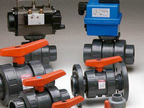
- Isolation Valve.
- Check Valve.
- Injection Valve.
- Air vent valve or pressure relief valve, where necessary.
- Suction Filter/Foot Valve.
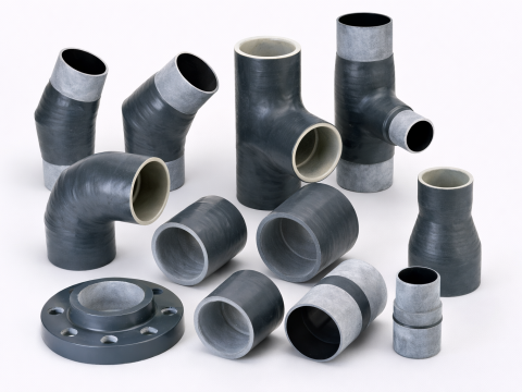
- Pipes and fittings compatible with the chemical.
Piping and accessory materials must be selected based on the chemical concentration, temperature, and chemical compatibility of the medium.
For example, materials such as PVC, CPVC, PP, PVDF, PTFE, or stainless steel may be considered depending on the specific application.
2.4. Valves, Filters, and Protective Devices
In addition to the metering pump, the system requires supporting accessories to ensure that chemical dosing is performed under the appropriate operating conditions.
Commonly integrated devices include:
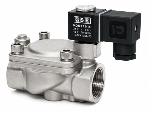
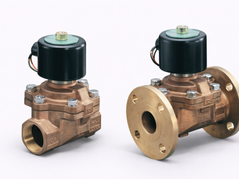
Back Pressure Valve: Creates the required back pressure at the discharge side, helping stabilize pump operation under suitable operating conditions.
Pressure Relief Valve: Protects piping and equipment when pressure exceeds the set value by releasing pressure according to the system design.
Pulsation Dampener: Reduces pressure and flow fluctuations caused by the pulsating flow characteristics of metering pumps.
Calibration Column: Supports the measurement and calibration of the actual metering pump flow rate.
Suction Filter: Retains solid particles that may affect the pump head and valves.
The integration of these devices depends on the pump type, pressure, flow rate, and operating requirements of the system.
2.5. Measuring and Monitoring Instruments
For automatic Dosing Systems, measuring instruments provide input signals that allow the PLC to monitor and control the chemical injection process.
Depending on the application, the system may incorporate:
- pH Sensor/Transmitter.
- ORP Sensor/Transmitter.
- Flow Meter.
- Pressure Transmitter.
- Level Sensor.
- Conductivity Sensor.
Depending on the process, signals from these instruments can be used to adjust the pump flow rate, activate alarms, or stop the system when abnormal conditions are detected.
2.6. Electrical Control Panel and PLC System
The electrical control panel serves as the central control unit for the Chemical Dosing System.
The control panel may include:
- PLC.
- HMI.
- MCCB/MCB.
- Contactor.
- Overload Relay.
- Intermediate relay.
- 24VDC power supply.
- Inverter or speed controller, if required.
- Terminal Block.
- Protective devices and wiring accessories.
The PLC receives signals from sensors, processes them according to the programmed logic, and sends control commands to the metering pumps or other related equipment.
The HMI allows operators to monitor system status, modify setting parameters, select operating modes, and check alarms.
3. FLEXIBLE SYSTEM DESIGN BASED ON METERING PUMP CAPACITY
3.1. Selection of Metering Pump Flow Rate
Flow rate is one of the most important parameters in Chemical Dosing System design.
The pump must deliver the required amount of chemicals per unit of time while allowing appropriate adjustment to suit operating conditions.
Commonly used flow rate units include:
- L/h.
- mL/min.
- L/min.
- m³/h.
When selecting a pump, the following parameters must be determined:
- Minimum dosing flow rate.
- Normal dosing flow rate.
- Maximum dosing flow rate.
- Pump adjustment range.
- Continuous or intermittent operating mode.
For example, if a process requires a chemical dosing rate of 10 L/h, the selected pump must have a suitable flow adjustment range for this operating point, rather than being selected solely based on its maximum flow rate.
ANCES can design the system configuration according to the metering pump capacity specified by the customer, ranging from low-flow pumps to higher-capacity pumps depending on the application.
3.2. Selection of Operating Pressure
In addition to flow rate, the pump discharge pressure must also be considered.
The metering pump must generate sufficient pressure to deliver chemicals to the injection point while overcoming pressure losses in the piping system and the pressure at the chemical injection location.
The following factors should be considered:
- Pressure at the injection point.
- Piping length.
- Pipe diameter.
- Elevation difference between the tank and injection point.
- Pressure losses across valves and fittings.
- Chemical characteristics.
Flow rate and pressure must be evaluated together to ensure the correct pump model is selected.
3.3. Design Based on the Number of Pumps and Chemical Injection Points
Depending on the process requirements, the system can be designed with different configurations.
Single Metering Pump System:
Suitable for applications requiring only one type of chemical to be injected at a single location.
Two-Pump Metering System:
Can be designed with one duty pump and one standby pump, or with two pumps operating alternately.
Multiple Metering Pump System:
Suitable for processes requiring multiple types of chemicals or multiple injection points.
Each pump can be controlled independently or integrated into the same PLC program.
3.4. Selection of Chemical Wetted Materials
The materials used for the pump head, diaphragm, valves, seals, and piping must be compatible with the chemicals being handled.
Common materials include:
| Material | Characteristics and Applications to Consider |
|---|---|
| PVC | Suitable for certain chemicals and specific temperature and pressure conditions |
| PP | Used in many chemical dosing applications |
| PVDF | Offers good chemical resistance in many environments |
| PTFE | A sealing material with broad chemical resistance |
| EPDM | Suitable for certain media and operating conditions |
| FKM | Selected for certain compatible chemical environments |
| SUS304/SUS316 | Used where the chemical characteristics permit |
No single material is suitable for all chemicals. Material selection must be based on concentration, temperature, pressure, and the manufacturer’s chemical compatibility chart.
3.5. Dosing Flow Rate Adjustment Capability
Depending on the pump type and control method, the chemical flow rate can be adjusted through:
- Stroke Length adjustment.
- Stroke Frequency adjustment.
- Motor speed control.
- 4–20 mA Analog signal.
- Pulse Signal.
- PLC control signal.
For automatic systems, the PLC can modify the control signal based on actual measured values or preset operating parameters.
4. EQUIPMENT BRAND SELECTION ACCORDING TO CUSTOMER REQUIREMENTS
4.1. Selection of Metering Pump Brands
One of the flexible features of ANCES-designed Dosing Systems is that customers can specify the metering pump brand according to their requirements.
Depending on plant standards, budget, and technical conditions, the following brands can be considered:
- ProMinent: Metering pumps and chemical treatment equipment.
- SEKO: Metering pumps and chemical dosing systems.
- Iwaki: Metering pumps and chemical pumps.
- Tacmina: Precision metering pumps.
- EMEC: Metering pumps and chemical dosing control equipment.
The list of brands can be expanded based on specific customer requirements and equipment availability.
Brand selection should not be based solely on the manufacturer’s name. The model, flow rate, pressure, pump head materials, and compatibility with the control system must also be considered.
4.2. Selection of Valves and Piping Accessories
Customers can specify particular brands or standards for auxiliary equipment, such as:
- Ball Valve.
- Check Valve.
- Pressure Reducing Valve.
- Pressure Relief Valve.
- Injection Valve.
- Back Pressure Valve.
- Pulsation Dampener.
These components are selected based on connection size, operating pressure, material, and chemical compatibility.
4.3. Selection of Measuring Instruments
Depending on monitoring and control requirements, the system can integrate measuring instruments from different manufacturers.
Examples include:
- pH Sensor.
- ORP Sensor.
- Flow Meter.
- Pressure Sensor.
- Level Sensor.
- Conductivity Sensor.
Measuring instruments can provide signals directly to the PLC for automatic control or generate alarms when measured parameters exceed preset limits.
4.4. Customizing Equipment Configuration Based on Budget and Technical Requirements
Not all systems require the same equipment configuration.
For basic applications, customers can select a simple control configuration consisting of metering pumps and essential auxiliary equipment.
For more complex processes, the system can be integrated with a PLC, HMI, measuring sensors, automatic control, and interlock functions.
ANCES can work with customers to select a suitable configuration based on:
- Process requirements.
- Preferred equipment brands.
- Technical specifications.
- Investment budget.
- Installation conditions.
- Compatibility with existing systems.
5. ELECTRICAL CONTROL PANEL DESIGN AND PLC PROGRAMMING ACCORDING TO REQUIREMENTS
5.1. Electrical Control Panel Design for Chemical Dosing Systems
The electrical control panel is designed to manage the power supply, control metering pumps, and monitor equipment within the system.
Depending on the number of pumps and operating requirements, the control panel can be designed with:
- Power supply and protective devices.
- Contactors and Overload Relays.
- Speed controller or inverter, if required.
- PLC.
- HMI.
- 24VDC power supply.
- Intermediate relays.
- Status indicator lights.
- Push buttons and mode selector switches.
- Signal connection terminals.
The control panel design must be suitable for equipment power ratings, installation environments, and the plant’s electrical voltage standards.
5.2. PLC Programming Based on Operating Procedures
The PLC is the central controller that processes input signals and controls the operation of the Chemical Dosing System.
Importantly, the PLC program does not have to be identical for every system. It can be developed according to each customer’s operating procedures, process requirements, and preferred control methods.
Possible functions include:
- Pump start and stop.
- Pump control in Auto/Manual mode.
- Time-based pump control.
- Flow signal-based control.
- pH or ORP signal-based control.
- Alternating pump operation.
- Chemical tank level monitoring.
- Fault alarms and protective interlocks.
5.3. Metering Pump Control in Auto/Manual Modes
The system can be designed with two basic operating modes.
Manual Mode:
Operators can manually start or stop the pumps using switches or the HMI interface.
This mode is commonly used for equipment inspection, maintenance, or system testing.
Auto Mode:
The PLC controls pump operation according to the programmed logic.
For example, pumps can automatically operate based on time schedules, signals from measuring instruments, or the status of the process system.
Switching between these two modes provides operators with greater flexibility during system operation and equipment inspection.
5.4. Control Based on Signals from Measuring Instruments
For Dosing Systems requiring automation, the PLC can receive signals from measuring instruments to adjust pump operation.
For example:
pH-Based Control:
When the pH value exceeds the preset range, the PLC can control the Acid or NaOH dosing pump according to the configured logic.
ORP-Based Control:
The ORP signal is used as a basis for adjusting the amount of oxidizing or reducing chemicals in suitable processes.
Flow-Based Control:
The PLC receives the water flow signal and adjusts the chemical dosing rate according to the preset ratio.
For example, when the water flow rate increases, the system can proportionally increase the chemical dosing rate if the process requires flow-proportional dosing.
These control modes must be designed based on chemical characteristics, reaction time, and the control requirements of each process.
5.5. Alarm Configuration and Protective Interlocks
To support safe operation, the PLC program can incorporate alarm and interlock functions.
Some conditions that can be monitored include:
- Low chemical tank level.
- Metering pump fault.
- Motor overload.
- Abnormal piping pressure.
- No flow signal.
- pH or ORP value exceeding preset limits.
- Power supply failure or loss of instrument signal.
Depending on the level of criticality, the PLC can generate an alarm, stop the pump, or switch to standby equipment.
The protective logic must be agreed upon with the customer during the design stage.
5.6. Customizing the HMI Interface and Operating Parameters
The HMI allows operators to monitor system status and modify permitted operating parameters.
The interface can display information such as:
- Operating status of each pump.
- Preset dosing flow rate.
- Actual pH/ORP values.
- Chemical tank level.
- Auto/Manual mode.
- Operating time.
- Alarms and fault history.
The HMI interface can be designed with a layout and language suitable for the customer’s requirements.
6. OPERATING PRINCIPLE OF A CHEMICAL DOSING SYSTEM
6.1. Chemical Supply Process
Chemicals are stored in the storage tank and supplied to the metering pump suction port through the suction line.
Before entering the pump, the chemical may pass through a suction filter or other necessary accessories, depending on the system configuration.
Basic process:
Chemical Tank → Suction Line → Suction Filter → Metering Pump
The metering pump draws chemicals from the tank and prepares to deliver them to the injection point.
6.2. Chemical Metering and Injection Process
After drawing in the chemical, the pump generates pressure to discharge it through the discharge line to the injection point.
Process:
Metering Pump → Discharge Line → Injection Valve → Process Pipeline
The amount of chemical delivered depends on the pump flow rate, operating pressure, and control mode.
Accessories such as Check Valves, Back Pressure Valves, and Pressure Relief Valves can be installed according to design requirements to support system operation.
6.3. Automatic Control Process
When the system operates in Auto Mode, the PLC executes the configured control program.
A basic operating sequence may be as follows:
- The PLC checks the conditions required for startup.
- The PLC checks the chemical level signal and equipment status.
- The metering pump starts according to the configured operating mode.
- Signals from measuring instruments are received, if available.
- Pump operation is adjusted according to the programmed logic.
- The system status is monitored, and alarms are generated when faults occur.
Depending on the requirements, the system can operate based on time, Analog signals, flow rate, or sensor measurement values.
6.4. Monitoring and Alarms During Operation
During operation, the PLC continuously monitors the connected signals.
If an abnormal condition is detected, the program can display an alarm on the HMI, activate an indicator light, or stop the equipment according to the protective logic.
This allows operators to identify the system status and respond to faults in a timely manner.
7. PRACTICAL APPLICATIONS OF CHEMICAL DOSING SYSTEMS
7.1. Raw Water Treatment Systems
In raw water treatment systems, chemicals are used to support coagulation, pH adjustment, oxidation, and disinfection processes.
The Chemical Dosing System can be designed to inject PAC, Polymer, NaOH, acid, or other chemicals suitable for the treatment process.
The dosing flow rate is determined based on inlet water quality, treatment flow rate, and required outlet water quality.
7.2. Wastewater Treatment Systems
Wastewater treatment systems often use different types of chemicals at various treatment stages.
Common applications include:
- Acid or NaOH dosing for pH adjustment.
- PAC dosing for coagulation.
- Polymer dosing to support flocculation.
- Oxidizing or reducing chemical dosing.
- Disinfectant dosing.
For systems with multiple treatment stages, several independent Dosing units can be designed and integrated into a common PLC control panel.
7.3. RO and Pure Water Treatment Systems
In RO systems, certain chemicals are used to protect membranes and control operating conditions.
Common Dosing applications include:
- Antiscalant dosing upstream of RO membranes.
- Sodium Bisulfite dosing for dechlorination when required.
- pH adjustment according to process requirements.
- Membrane cleaning chemical dosing in suitable CIP procedures.
The Chemical Dosing System must be designed based on feed water flow rate, chemical concentration, and the dosing requirements specified by the chemical or RO membrane manufacturer.
7.4. Cooling Tower and Boiler Systems
For Cooling Tower systems, Chemical Dosing Systems can be used to inject chemicals that control scale formation, corrosion, and microbiological growth in circulating water.
For Boiler systems, chemicals can be injected into feedwater or other suitable points in the system to control water chemistry and minimize problems associated with scale formation and corrosion.
Depending on plant capacity, the system can use one or multiple metering pumps integrated with sensors and automatic control programs.
7.5. Chemical Dosing Processes in Manufacturing Plants
In addition to water treatment applications, Chemical Dosing Systems are also used in various manufacturing processes that require chemicals to be supplied at specified flow rates.
Examples include:
- Chemical dosing in proportion to raw materials.
- Additive dosing into mixing tanks.
- Solution supply to production lines.
- Periodic chemical metering.
- Chemical injection at multiple points within the same production line.
For these applications, the PLC program can be developed according to the process sequence and the customer’s specific operating requirements.
8. FACTORS TO CONSIDER WHEN DESIGNING A CHEMICAL DOSING SYSTEM
8.1. Chemical Characteristics
This is an important factor when selecting pumps, storage tanks, piping, and accessories.
The following information should be identified:
- Chemical name.
- Concentration.
- Temperature.
- Corrosiveness.
- Viscosity.
- Potential for crystallization or sediment formation.
- Material compatibility.
Selecting unsuitable materials may result in leakage, equipment damage, or reduced system service life.
8.2. Dosing Flow Rate and Pressure
The required chemical flow rate and pressure at the injection point must be accurately determined.
These two parameters provide the basis for metering pump selection and piping design.
In addition, the pump adjustment range must be considered to ensure that the equipment can accommodate both normal operating conditions and variations in process load.
8.3. Installation Conditions
The system design must be suitable for the actual plant layout.
Factors to consider include:
- Available installation area.
- Chemical storage tank location.
- Distance between the tank and pump.
- Suction lift and piping length.
- Injection point location.
- Accessibility for maintenance.
- Environmental conditions and ventilation.
For hazardous or highly corrosive chemicals, additional consideration must be given to containment, ventilation, and appropriate safety measures.
8.4. Automation Requirements
Before designing the electrical control panel and programming the PLC, the desired operating method must be clearly defined.
For example:
- Should the pump operate manually or automatically?
- Should the pump run continuously or periodically?
- Should control be based on time or sensor signals?
- Is alternating pump operation required?
- Is connection to the plant’s central PLC required?
- Is remote monitoring required?
Defining these requirements from the beginning helps ensure that the control program is suitable for actual operating procedures.
8.5. Expansion and Maintenance Capability
A Chemical Dosing System should be designed with adequate access to equipment for inspection and maintenance.
Depending on requirements, the following provisions can be considered:
- Reserved installation space for additional pumps.
- Spare PLC input/output capacity.
- Piping layout that facilitates replacement.
- Quick-disconnect connections at suitable locations.
- Reserved space for control panel expansion.
- Isolation valves for individual equipment maintenance.
These provisions help make the system more flexible when the plant changes its capacity or expands its production process.
9. CHEMICAL DOSING SYSTEM DESIGN AND IMPLEMENTATION PROCESS
To ensure that a Chemical Dosing System meets technical and operational requirements, the implementation process should be carried out step by step.
9.1. Collection of Technical Requirements
First, basic information must be collected from the customer:
- Purpose of chemical dosing.
- Chemical type and concentration.
- Required dosing flow rate.
- Pressure at the injection point.
- Number of injection points.
- Preferred equipment brands.
- Control and monitoring requirements.
This information provides the basis for determining the system configuration.
9.2. Site Survey and Determination of Operating Parameters
After collecting the requirements, the installation conditions and process flow must be assessed.
The site survey may include:
- Chemical tank location.
- Distance to the injection point.
- Electrical power supply conditions.
- Existing control signals.
- Available space for the Dosing unit.
- Compatibility with the plant’s automation system.
9.3. Equipment Configuration Design
Based on the technical information, the system is designed with suitable components.
The configuration may include:
- Chemical storage tank.
- Metering pump.
- Valves and accessories.
- Piping.
- Measuring instruments.
- Skid frame.
- Electrical control panel.
Customers can select equipment brands according to their requirements and approve the configuration before implementation.
9.4. Electrical Control Panel Design and PLC Programming
After the equipment configuration has been determined, the electrical control panel is designed and the control program is developed.
Auto/Manual functions, time-based control, measurement signal-based control, alarms, and interlocks are programmed according to the agreed operating requirements.
The HMI interface can also be customized to make monitoring and operation more convenient for users.
9.5. Assembly, Inspection, and Testing
After the design is completed, the equipment is assembled into an integrated system.
Inspection and testing may include:
- Checking piping connections.
- Checking for leakage.
- Checking the power supply and electrical connections.
- Checking the operation of each pump.
- Checking sensor signals.
- Checking the PLC program.
- Testing alarm and interlock functions.
Testing must be carried out in accordance with procedures suitable for the chemical characteristics and safety conditions at the plant.
9.6. Handover and Operating Instructions
After inspection and completion, the system is handed over together with the necessary technical information.
Handover documentation may include:
- Operating instructions.
- Electrical diagrams.
- Piping diagrams.
- Equipment list.
- Setting parameters.
- Inspection and maintenance instructions.
Operators are instructed on basic operating procedures, Auto/Manual mode selection, and how to handle common alarms.
10. ANCES – CUSTOM CHEMICAL DOSING SYSTEM DESIGN AND INSTALLATION SOLUTIONS
With the increasingly diverse use of chemicals in industrial plants, a Dosing System must be designed to suit the process rather than applying one fixed configuration to every application.
ANCES provides consulting, design, and installation solutions for custom Chemical Dosing Systems, focusing on equipment customization and control methods according to the customer’s actual operating conditions.
The scope of implementation may include:
Flexible Design Based on Metering Pump Capacity
The system is designed based on chemical dosing flow rate, pressure, and operating mode. Customers can request a configuration with one, two, or multiple metering pumps, depending on the process requirements.
Equipment Brand Selection According to Customer Requirements
Metering pumps, valves, accessories, sensors, and measuring instruments can be selected according to the brands, technical standards, and procurement requirements of each plant.
Electrical Control Panel Design and PLC Programming According to Requirements
The PLC program is developed based on actual operating procedures and can integrate Auto/Manual modes, sensor signal-based control, alternating pump operation, alarms, and protective interlocks.
System Integration and Operating Support
Equipment is arranged into an integrated system for convenient installation, connection, inspection, and maintenance.
With an application-specific design approach, ANCES aims to provide Dosing solutions that meet the technical, equipment configuration, and control requirements of water treatment systems and industrial processes.
11. CONCLUSION
Chemical Dosing Systems are an important part of many water treatment and industrial manufacturing processes. Proper system design helps control the amount of chemicals supplied to the process, supports the maintenance of operating conditions, and reduces dependence on manual dosing operations.
An effective Dosing System requires an integrated assessment of the storage tank, metering pump, piping, valves and accessories, measuring instruments, electrical control panel, and PLC control program.
In particular, the ability to design flexibly based on metering pump capacity, select equipment brands according to customer requirements, and develop PLC programs based on specific operating procedures enables the system to better accommodate the differences between industrial plants.
Through its custom design and installation solutions, ANCES aims to develop Chemical Dosing Systems suitable for individual applications, ranging from simple chemical injection units to multi-pump systems integrated with automatic control.
Customers can provide information about the chemical type, dosing flow rate, pressure, preferred equipment brands, and control requirements so that ANCES can recommend a suitable system configuration.