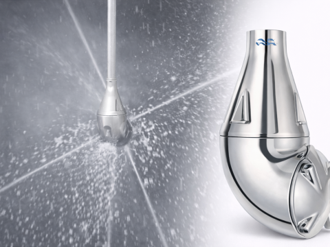
Automatic Pressure Reducing Valve RI and Pressure Relief Valve VS – Effective Pressure Control Solution for Industrial Systems
09/06/2026In industrial systems handling water, compressed air, and steam, maintaining stable pressure is essential for operational efficiency and equipment protection. RI automatic pressure reducing valves and VS pressure relief valves provide fully automatic pressure control using the energy of the process medium itself, without requiring electrical power or auxiliary pneumatic control. With high accuracy, robust construction, and versatile application capabilities, these valves are ideal solutions for modern industrial systems.
1. What is an Automatic Pressure Reducing Valve?
In industrial piping systems, unstable pressure can affect operating performance, reduce equipment service life, and create potential safety risks. Therefore, pressure control is always an important requirement in systems using water, compressed air, and steam.
An automatic pressure reducing valve is a device designed to maintain the outlet pressure at a desired set value regardless of changes in inlet pressure. The valve operates entirely by utilizing the energy of the process medium itself and does not require electrical power or an external pneumatic control source.
In addition, an automatic pressure relief valve helps maintain a minimum system pressure or protect the system from overpressure conditions by automatically opening when the pressure exceeds the preset value.
2. Introduction to RI Pressure Reducing Valve and VS Pressure Relief Valve
The RI series is an automatic pressure reducing valve designed to reduce and stabilize downstream pressure. The valve is suitable for various media such as water, air, and steam.
The VS series is an automatic pressure relief valve or pressure sustaining valve whose function is to protect the system by relieving excess pressure or maintaining a minimum pressure at a specified point within the pipeline.
Both valve series utilize a direct diaphragm-operated mechanism, providing high accuracy and stable operation over a long service life.
3. Construction of the Automatic Pressure Reducing Valve
The valve is designed with a robust structure and high durability, consisting of the following main components:
Valve Body
Manufactured from cast iron or cast steel materials capable of withstanding industrial operating pressures.
Control Diaphragm
This is the key component responsible for sensing pressure variations and controlling valve movement.
Pressure Adjusting Spring
Allows adjustment of the required operating pressure according to system requirements.
Valve Disc and Valve Seat
Responsible for opening, closing, and regulating the flow of the process medium through the valve.
Bolts and Connecting Components
Designed to provide reliable sealing performance and long-term durability.
4. Operating Principle
4.1 Operating Principle of the RI Pressure Reducing Valve
The RI pressure reducing valve operates based on the balance between the preset spring force and the downstream pressure acting on the diaphragm.
When the downstream pressure falls below the set value, the valve automatically opens further to increase flow and raise the pressure to the desired level.
Conversely, when the downstream pressure rises above the set value, the valve automatically reduces the flow passage area in order to decrease the pressure to the preset value.
Through this mechanism, the downstream pressure is continuously maintained at a stable level even when the inlet pressure changes.
4.2 Operating Principle of the VS Pressure Relief Valve
The VS valve monitors system pressure through the control diaphragm.
When the pressure exceeds the preset value, the force acting on the diaphragm overcomes the spring force, causing the valve to open and discharge part of the process medium.
When the pressure returns to a safe operating level, the valve automatically closes.
This operating principle helps protect pipelines, equipment, and critical system components from overpressure conditions.
5. Outstanding Technical Features
Nominal Size Range
- DN15 to DN150
Applicable Media
- Water
- Compressed air
- Steam
Operating Temperature
- Up to 240°C
Pressure Adjustment Range
- Various pressure ranges available to suit different applications
Connection Types
- Threaded connection
- Flanged connection
Operating Method
- Fully automatic operation
- No electrical power required
- No auxiliary pneumatic control source required
6. Advantages of Automatic Pressure Control Valves
No Electrical Power Required
Helps reduce operating costs and improve safety in industrial environments.
Accurate Pressure Control
Maintains stable pressure even when flow rate or inlet pressure fluctuates.
High Durability
Robust design suitable for high-temperature and high-pressure applications.
Easy Installation
No complex control system is required.
Reduced Maintenance Cost
A simple structure with fewer moving parts helps increase service life.
Effective System Protection
Prevents overpressure conditions and reduces the risk of equipment damage.
7. Industrial Applications
RI pressure reducing valves and VS pressure relief valves are widely used in various industries:
Steam Systems
Controlling steam pressure supplied to heat exchangers and production processes.
Water Supply Systems
Maintaining stable pressure throughout the distribution network.
Compressed Air Systems
Adjusting pressure according to the requirements of pneumatic equipment.
Food and Beverage Plants
Ensuring stable operating pressure for production lines.
Chemical Plants
Protecting systems against abnormal pressure fluctuations.
Power Generation Facilities
Applied in high-pressure water and steam systems.
8. Guidelines for Selecting the Appropriate Valve
To select the correct valve, the following factors should be considered:
Process Medium
- Water
- Air
- Steam
Inlet Pressure
Determine the maximum operating pressure of the system.
Required Pressure
Select the appropriate adjustment range according to operating requirements.
Flow Rate
Ensure that the valve capacity meets the actual system flow demand.
Pipeline Size
Select a valve size corresponding to the existing piping system.
9. Installation and Maintenance
Installation
- Install the valve according to the flow direction indicated on the valve body.
- Ensure that the pipeline is clean before installation.
- It is recommended to install a strainer upstream of the valve to protect internal components.
- Provide sufficient space for inspection and maintenance activities.
Maintenance
- Periodically inspect the diaphragm condition.
- Clean internal components when necessary.
- Check the tightness of connections and sealing gaskets.
- Readjust the pressure setting if operating conditions change.
10. Conclusion
RI automatic pressure reducing valves and VS pressure relief valves provide an effective solution for controlling and maintaining stable pressure in industrial systems. With fully automatic operation, no electrical power requirement, high accuracy, and outstanding durability, these valve series are widely used in water, compressed air, and steam applications.
Selecting and installing the correct valve not only improves operating efficiency but also helps protect equipment, reduce maintenance costs, and extend the service life of the entire system.