Industrial Electrical Control Cabinets – Automated Control Solutions for Motors, PLC Systems, Water Treatment, RO Systems, Chemical Dosing, and Production Lines
24/08/2026In modern factories and industrial production systems, requirements for automation, precise control, and stable operation are becoming increasingly important. Equipment such as motors, pumps, fans, valves, mixers, sensors, and water treatment systems can be difficult to operate manually while maintaining the required levels of productivity, accuracy, and process control.
An industrial electrical control cabinet serves as the central connection and control point for equipment within a system. Depending on the application, the cabinet can integrate PLCs, HMIs, variable frequency drives (VFDs), soft starters, contactors, relays, sensors, and other components to perform control, monitoring, and protection functions.
The following article provides an overview of industrial control cabinets, their common types, and specific applications including motor control cabinets, PLC control cabinets, wastewater treatment control cabinets, RO system control cabinets, hot & cold alcohol filling system control cabinets, automatic chemical dosing control cabinets, and DI water pressure-boosting pump control systems.
1. What Is an Industrial Control Cabinet?
An electrical control cabinet is an assembly of electrical equipment, control devices, and protective devices installed inside an enclosure to perform control, monitoring, protection, and automation functions for machinery or industrial processes.
A control cabinet can be considered the control center of a system, where signals from sensors, switches, or external devices are received and processed by a controller before control commands are sent to the actuators.
For example, in a water treatment system, the PLC inside the control cabinet can receive signals from level sensors, pressure sensors, flow meters, or water quality monitoring instruments. The PLC then processes these signals and controls pumps, valves, mixers, blowers, or chemical dosing pumps according to the programmed sequence.
An industrial control cabinet can be used to operate:
- Motors and pumps;
- Fans and blowers;
- Solenoid valves and control valves;
- Dosing pumps;
- Mixers and agitators;
- RO systems;
- Wastewater treatment systems;
- Production lines;
- Filling systems;
- Automatic chemical dosing systems;
- Pressure-boosting pump systems.
As a result, operators do not need to manually control each individual device and can instead manage the entire process through an HMI or centralized supervisory control system.
2. The Role of Control Cabinets in Industrial Plants
A control cabinet does not simply perform equipment switching functions. It can also perform many other important functions.
2.1. Equipment Control
The control cabinet provides control signals for operating equipment such as motors, pumps, fans, valves, and mixers.
Depending on the system design, equipment can be controlled:
- By push buttons;
- Through an HMI;
- Automatically by PLC;
- According to sensor signals;
- According to preset time schedules;
- According to pressure, flow rate, liquid level, or temperature.
2.2. Equipment Protection
The control cabinet can integrate protective devices to minimize the effects of:
- Overload;
- Short circuit;
- Phase loss;
- Phase sequence/reversal;
- Overvoltage;
- Undervoltage;
- Other abnormal operating conditions.
2.3. System Monitoring
When combined with a PLC and HMI, the operator can monitor:
- Pump status;
- Motor status;
- Pressure;
- Flow rate;
- Liquid level;
- Temperature;
- Sensor signals;
- Alarm conditions.
This allows abnormal conditions to be detected at an early stage and reduces troubleshooting time.
2.4. Process Automation
This is one of the most important functions of a control cabinet.
Instead of requiring operators to perform each step manually, the PLC can execute the entire operating sequence according to the programmed logic.
For example:
Low-level signal → PLC receives signal → Pump starts → Water reaches preset level → PLC stops the pump.
Or:
Flow rate increases → PLC adjusts VFD speed → Pump speed changes → System pressure is maintained at the required level.
3. Basic Construction of an Electrical Control Cabinet
An industrial control cabinet generally consists of two main parts: the cabinet enclosure and the electrical/control equipment installed inside.
3.1. Electrical Cabinet Enclosure
The enclosure protects all internal equipment against environmental influences.
Depending on the application, the enclosure can be manufactured from:
- Powder-coated steel;
- Galvanized steel;
- Stainless steel;
- Other materials suitable for the installation environment.
The enclosure must provide sufficient mechanical strength, adequate protection for internal equipment, and convenient access for cable routing and maintenance.
In environments with high humidity or stringent hygiene requirements, the enclosure material and ingress protection rating should be selected according to the actual operating conditions.
3.2. Switching and Protection Devices
These may include:
- MCBs;
- MCCBs;
- ACBs;
- RCBOs;
- Contactors;
- Protective relays;
- Overload relays.
These devices are used for switching and protecting electrical circuits within the cabinet.
3.3. PLC
The PLC is the central controller in many automation control cabinets.
The PLC receives input signals from sensors and external equipment, processes these signals according to the programmed logic, and then generates output signals to control the actuators.
3.4. HMI
The HMI is the interface between the operator and the control system.
Through the HMI, operators can:
- Start/stop equipment;
- Monitor process parameters;
- Set operating values;
- View alarms;
- Monitor equipment status.
3.5. Variable Frequency Drive
A Variable Frequency Drive (VFD) is used to control motor speed and operating frequency.
In pumping systems, a VFD is particularly useful when the system needs to maintain stable pressure or flow according to actual demand.
3.6. Soft Starter
A Soft Starter helps control motor starting and reduce starting current and mechanical stress during the starting process.
It can be applied to motors where controlled starting is required.
3.7. Control Power Supply
A 24 VDC power supply is commonly used to supply:
- PLCs;
- Sensors;
- Relays;
- HMIs;
- Other control devices.
3.8. Terminal Blocks and Wiring System
Terminal blocks, cable ducts, control cables, power cables, and wiring accessories help organize the cabinet wiring in a systematic manner, making inspection and maintenance more convenient.
4. Motor Control Cabinet
A motor control cabinet is designed to control and protect electric motors used in industrial plants.
This type of cabinet is commonly used for:
- Water pumps;
- Fans;
- Compressors;
- Mixers;
- Blowers;
- Conveyors;
- Crushers;
- Other rotating industrial equipment.
Depending on motor capacity and operating requirements, various starting methods can be used.
Direct-On-Line Starting
This method has a relatively simple configuration and is suitable for motors and systems where starting requirements are not particularly demanding.
Star-Delta Starting
The star-delta starting method is used to reduce the starting current compared with direct-on-line starting in suitable applications.
Soft Starting
A Soft Starter helps control the motor starting process and reduce mechanical impact on the motor and associated equipment.
VFD Starting and Speed Control
A VFD not only supports motor starting but also allows motor speed to be adjusted according to process requirements.
For example, in a pumping system, motor speed can be adjusted according to the required pressure or flow rate.
5. PLC Electrical Control Cabinet
A PLC control cabinet is an automation solution based on a Programmable Logic Controller (PLC).
Compared with a basic control cabinet using only contactors and relays, a PLC control cabinet can process multiple signals and execute more complex control sequences.
A typical PLC control system can be represented as:
Sensors → Input Modules → PLC → Output Modules → Actuators
For example:
A pressure sensor sends a signal to the PLC. The PLC compares the actual pressure with the preset pressure value. If the pressure is too low, the PLC sends a command to the VFD to increase pump speed. When the pressure reaches the required value, the PLC adjusts the pump speed to maintain stable pressure.
A PLC control cabinet can be integrated with an HMI and SCADA system to provide expanded monitoring and management capabilities.
This solution is suitable for systems requiring automatic control, high accuracy, and future expandability.
6. Control Cabinet for Coal Separation System of Thermal Power Plant Incinerator
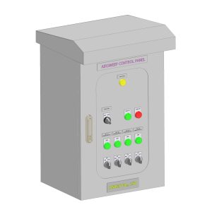
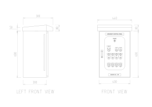
The control cabinet for the coal separation system of a thermal power plant incinerator is a specialized electrical control solution designed to control and monitor the coal separation, feeding, and conveying system before the coal enters the combustion chamber. This system requires stable and continuous operation under the specific operating conditions of the power generation industry.
The control cabinet is designed to control the operating sequence of equipment within the coal separation system, ensuring a stable supply of fuel to the combustion chamber, minimizing blockage or uneven coal feeding, and thereby supporting stable combustion conditions and the thermal efficiency of the incinerator.
Main Functions of the Control Cabinet
Depending on the actual system configuration, the coal separation system control cabinet can perform the following functions:
- Control of coal separation and feeding equipment: Controls the equipment involved in coal separation, conveying, and feeding into the combustion chamber.
- Sequential operation control: Equipment is started, operated, and stopped according to a predefined sequence to minimize incorrect operation or adverse effects on the overall system.
- Equipment status monitoring: Indicator lights and control devices installed on the cabinet door allow operators to easily identify the operating status of individual equipment.
- Electrical system protection: Integrates appropriate switching and protection devices to minimize the effects of overload, short circuit, or other electrical faults during operation.
- Fault indication: Supports the detection and indication of abnormal operating conditions, allowing operators to quickly inspect and take corrective action.
- Continuous operation: The cabinet is designed to meet the requirements for continuous operation of the system under industrial operating conditions.
7. RO System Control Cabinet
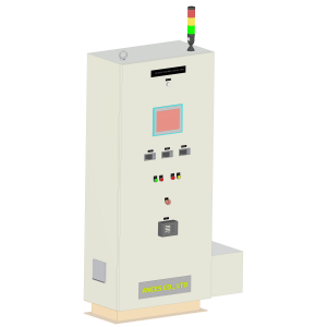
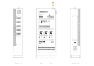
A Reverse Osmosis (RO) system consists of multiple pieces of equipment that need to operate in coordination. Therefore, the control cabinet plays an important role in system operation.
An RO control cabinet can control:
- Feed water pumps;
- High-pressure pumps;
- Electric valves;
- Automatic valves;
- Chemical dosing pumps;
- Flushing systems;
- CIP systems, depending on the configuration.
The control cabinet can also receive signals such as:
- Pressure;
- Flow rate;
- Conductivity;
- TDS;
- Water level;
- Equipment status.
Through the PLC and HMI, operators can monitor the operating condition of the RO system and select different operating modes.
A properly designed RO system should not only provide equipment control but also incorporate appropriate interlocks and protection conditions to prevent operation under abnormal conditions.
8. Hot & Cold Alcohol Filling System Control Cabinet
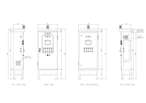
In beverage production lines, filling systems require accurate control of various parameters to ensure stable production.
A hot & cold alcohol filling system control cabinet can be designed to control and monitor:
- Product transfer pumps;
- Valves;
- Flow rate;
- Temperature;
- Tank level;
- Filling sequence;
- Related actuators.
For Hot Filling applications, particular attention should be paid to temperature control and the operating sequence.
For Cold Filling, temperature conditions, flow rate, and the product supply sequence must also be controlled according to the requirements of the production line.
The PLC can be programmed to execute the complete filling sequence, while the HMI allows operators to monitor and configure operating parameters.
9. Automatic Chemical Dosing System Control Cabinet
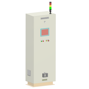
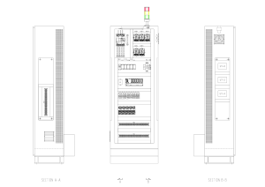
In water treatment systems, accurate chemical dosing is essential.
An automatic chemical dosing control cabinet is responsible for controlling dosing pumps according to predefined operating conditions.
The system may use signals from:
- Water flow rate;
- pH;
- ORP;
- Chemical tank level;
- Signals from the main PLC control system.
For example, when the water flow rate changes, the PLC can adjust the control signal to the dosing pump to modify the chemical dosing rate.
In addition to control functions, the cabinet can provide alarms for conditions such as:
- Low chemical level;
- Pump fault;
- Sensor signal failure;
- Overload;
- Power supply failure.
This helps improve chemical dosing control and reduce manual intervention.
10. DI Water Pressure-Boosting Pump Control System for Product Rinsing
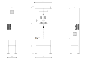
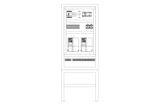
Deionized Water (DI Water) is commonly used in processes requiring high water quality, such as product rinsing and manufacturing processes with stringent water quality requirements.
In these systems, maintaining stable water pressure is an important factor.
A DI water pressure-boosting pump control cabinet can integrate:
- Pumps;
- Variable Frequency Drives;
- Pressure sensors;
- PLC;
- HMI;
- Motor protection devices.
The control principle can be represented as:
Pressure Sensor → PLC → VFD → Pump → Pressure Regulation
When water demand increases, the pipeline pressure tends to decrease. The PLC receives the signal from the pressure sensor and adjusts pump speed through the VFD.
When demand decreases, pump speed can be reduced accordingly.
This control method allows the system to respond more flexibly to changes in demand and helps prevent the pump from continuously operating at maximum speed.
11. Industrial Applications of Control Cabinets
Industrial control cabinets can be applied across a wide range of industries.
Manufacturing Plants
Used for controlling production lines, motors, pumps, fans, machinery, and auxiliary equipment.
Water Treatment Systems
Applications include:
- RO systems;
- UF systems;
- DI water systems;
- Water supply systems;
- Wastewater treatment systems;
- Chemical dosing systems.
Food and Beverage Industry
Used for controlling:
- Storage tanks;
- Pumps;
- Valves;
- Filling systems;
- Heating/cooling systems.
Chemical Industry
Used for controlling dosing pumps, valves, mixers, and chemical supply systems.
HVAC Systems
Used for controlling fans, pumps, valves, and other HVAC-related equipment.
12. Important Considerations When Designing and Selecting a Control Cabinet
To ensure stable control cabinet operation, several factors should be considered during the design stage.
Proper Load Determination
The power rating and characteristics of motors, pumps, fans, and other electrical loads should be fully assessed.
Appropriate Equipment Selection
MCBs, MCCBs, contactors, overload relays, VFDs, PLCs, and other components should be selected according to the actual electrical and operating requirements.
Separation of Power and Control Circuits
Proper arrangement of power and control circuits helps facilitate installation and maintenance while reducing potential interference between circuits.
Heat Dissipation
Equipment such as VFDs and power supplies may generate heat during operation. The cabinet should therefore be equipped with an appropriate heat dissipation or ventilation solution.
Noise and EMI Considerations
For PLC cabinets, VFD systems, and systems containing multiple analog signals, proper wiring and component arrangement are important to minimize electrical interference.
Maintainability
The cabinet layout should allow technicians to easily:
- Inspect equipment;
- Perform electrical measurements;
- Replace components;
- Troubleshoot faults;
- Carry out preventive maintenance.
Future Expansion
If the system may increase in capacity or require additional equipment in the future, sufficient cabinet space, power capacity, and I/O points should be considered during the initial design.
13. Control Cabinet Design and Manufacturing Process
A customized control cabinet generally goes through the following basic stages:
Step 1: System Survey
Collect information about equipment, process requirements, power ratings, signals, and operating requirements.
Step 2: Control System Development
Determine the control method, operating sequence, interlocks, and protection conditions.
Step 3: Electrical Schematic Design
Develop power circuit diagrams, control circuit diagrams, I/O diagrams, and interlock circuits.
Step 4: Component Selection
Select PLCs, HMIs, VFDs, contactors, MCCBs, relays, power supplies, and other required components.
Step 5: Cabinet Layout Design
Arrange the internal components to ensure proper technical configuration and convenient maintenance.
Step 6: Fabrication and Assembly
Fabricate the cabinet enclosure, install components, DIN rails, cable ducts, terminal blocks, and wiring systems.
Step 7: PLC/HMI Programming
Develop the control program, operator interface, alarm functions, and automatic/manual operating modes.
Step 8: Inspection and Commissioning
Check electrical circuits, I/O signals, protection devices, PLC programs, and overall system operation.
Step 9: Handover
Hand over the control cabinet together with the necessary technical documentation and operating instructions.
14. Customized Control Cabinet Solutions
Each factory has its own process requirements, equipment configuration, and operating conditions. Therefore, instead of using one fixed cabinet configuration for every application, control cabinets can be engineered according to actual system requirements.
A complete solution can include:
- Electrical schematic design;
- Cabinet layout design;
- Component selection;
- Cabinet assembly;
- Electrical wiring;
- PLC programming;
- HMI development;
- VFD integration;
- Sensor integration;
- System commissioning;
- Handover and operator training.
Especially for systems such as wastewater treatment, RO, chemical dosing, DI water, or filling lines, the control cabinet should be designed based on the actual process requirements, rather than simply selecting electrical components according to equipment power ratings.
15. Conclusion
An industrial electrical control cabinet is an important component of modern factory automation, performing control, monitoring, protection, and equipment integration functions.
Depending on the application, the cabinet can be designed in various forms, including motor control cabinets, PLC control cabinets, wastewater treatment control cabinets, RO system control cabinets, hot & cold alcohol filling system control cabinets, automatic chemical dosing control cabinets, and DI water pressure-boosting pump control cabinets.
The key consideration in control cabinet design is not only the selection of electrical components but also ensuring that the control philosophy is properly matched with the actual process, while providing equipment protection, stable operation, effective monitoring, and convenient maintenance and future expansion.
For systems requiring a high level of automation, the integration of PLC – HMI – VFD – sensors – switching devices – and actuators can provide a complete control solution, reducing manual intervention and improving process control.
Therefore, a properly designed control cabinet from the beginning not only helps ensure reliable equipment operation but also provides a foundation for factories to gradually upgrade their systems toward advanced automation and centralized monitoring.