VENN RD-40 – AUTOMATIC STEAM PRESSURE REDUCING VALVE FOR PRECISE PRESSURE CONTROL IN INDUSTRIAL STEAM SYSTEMS
03/11/2026In industrial steam systems, the steam pressure from the supply source often needs to be adjusted before being delivered to steam-consuming equipment. If the inlet pressure is too high or unstable, downstream equipment may not operate under its designed conditions, while increasing the requirements for piping and pressure-containing components.
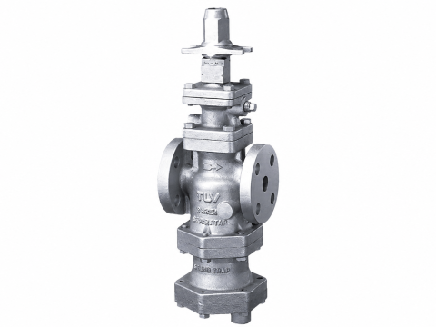
The VENN RD-40 Steam Pressure Reducing Valve is designed to automatically reduce the inlet steam pressure and maintain the secondary-side pressure within the set range. With its compact design, automatic adjustment mechanism, and multiple outlet pressure adjustment ranges, the VENN RD-40 is suitable for steam-consuming equipment such as food-processing machinery, medical equipment, industrial washing machines, heating equipment, and other steam-using equipment.
The VENN RD-40 is available in nominal sizes 15, 20, and 25, corresponding to 1/2″, 3/4″, and 1″ piping, and features a CAC406 Cast Bronze body with JIS Rc threaded connections. The valve provides three secondary pressure adjustment ranges: Type L: 0.02–0.25 MPa, Type M: 0.20–0.40 MPa, and Type H: 0.35–0.80 MPa.
1. OVERVIEW OF THE VENN RD-40 STEAM PRESSURE REDUCING VALVE
1.1. VENN – Japanese Industrial Valve Manufacturer
VENN CO., LTD. is a brand specializing in valves and equipment for steam, water, and industrial utility systems.
Within its pressure reducing valve range for steam applications, the RD-40, RD-41, and RD-41F series are designed for steam-using equipment requiring pressure control on the secondary side.
Among them, the RD-40 features a CAC406 body, threaded connections, and a compact design, making it suitable for steam piping from DN15 to DN25.
1.2. What Is the VENN RD-40 Steam Pressure Reducing Valve?
The VENN RD-40 is an automatic pressure reducing valve designed for steam service.
The main function of the valve is:
High-pressure Steam → VENN RD-40 → Lower and Controlled Steam Pressure
Instead of allowing steam from the supply source to flow directly to the steam-consuming equipment, the RD-40 is installed in the piping to reduce the pressure to a level suitable for the downstream equipment.
The secondary-side pressure can be adjusted through the valve’s pressure adjustment mechanism.
1.3. Role of a Pressure Reducing Valve in a Steam System
A steam system may include multiple steam-consuming devices requiring different operating pressures.
For example, the steam supply may be provided at a pressure higher than the pressure required by a heating device or process equipment. In such cases, reducing the pressure upstream of the equipment helps the system operate under a more suitable pressure condition.
The VENN RD-40 performs the following functions:
- Reduces steam pressure from the primary side to the secondary side.
- Maintains the secondary pressure within the adjustment range.
- Limits pressure fluctuations affecting downstream equipment.
- Supplies steam at conditions more suitable for the steam-consuming equipment.
1.4. Suitable Applications for the VENN RD-40
The VENN RD-40 is intended for steam-consuming equipment requiring relatively precise pressure adjustment.
Typical applications include:
- Food-processing machinery.
- Medical equipment.
- Industrial washing machines.
- Heating equipment.
- Industrial steam-consuming equipment.
- Steam piping systems with relatively small pipe sizes requiring automatic pressure reduction.
2. CONSTRUCTION OF THE VENN RD-40 STEAM PRESSURE REDUCING VALVE
2.1. Overall Construction
The VENN RD-40 features a compact pressure reducing valve construction, with the valve body installed in the piping and the pressure control assembly positioned above the body.
The main components can be divided into:
- Valve Body.
- Spring Case.
- Seat Ring.
- Seat Disc.
- Stem.
- Bellows.
- Handle.
- Bottom Plug.
- Adjusting Spring.
- Top Spring Seat.
- Adjusting Screw.
- Disc Spring.
- Strainer.
- Gasket.
- Bolt.
These components work together to form the pressure-reducing and secondary-pressure control mechanism.
2.2. Valve Body – Cast Bronze CAC406
The VENN RD-40 body is manufactured from CAC406, a cast bronze material.
The valve body is the main pressure-containing component and also forms the flow passage through which steam flows across the valve.
The CAC406 body combined with the compact construction makes the RD-40 suitable for DN15–DN25 steam piping systems.
2.3. Piston and Pressure Adjustment Mechanism
The internal mechanism is responsible for changing the opening condition of the throttling component according to the secondary-side pressure.
When the downstream pressure changes relative to the set pressure, the pressure-sensing mechanism acts on the stem, seat disc, and resilient components to regulate the amount of steam passing through the valve.
As a result, the secondary pressure can be maintained within the specified adjustment range.
2.4. Bellows – Pressure-Sensing Component
The Bellows is one of the important components in the pressure control mechanism.
The Bellows responds to changes in system pressure and transfers the resulting mechanical movement to the adjustment mechanism.
In the RD-40, the Bellows is made of SUS316L, providing a suitable material configuration for the pressure-sensing component under the valve’s operating conditions.
2.5. Seat and Disc
The Seat Ring and Seat Disc form the throttling and flow shut-off area.
According to the RD-40 material configuration:
- Seat Ring: SUS416.
- Seat Disc: SUS440C.
The combination of the seat and disc allows the valve to regulate the steam flow area in order to control the downstream pressure.
2.6. Spring and Pressure Adjustment Mechanism
The spring system inside the RD-40 generates a force opposing the force produced by the secondary-side pressure.
The main components include:
- Adjusting Spring.
- Top Spring Seat.
- Disc Spring.
- Adjusting Screw.
Adjustment of this mechanism allows the pressure setting range to be selected according to Type L, Type M, or Type H.
2.7. Stainless Steel Materials Used in Internal Components
In addition to the CAC406 body, the VENN RD-40 uses various stainless steel materials for its internal components.
| Component | Material |
|---|---|
| Valve Body | CAC406 |
| Spring Case | Aluminum Casting ADC |
| Seat Ring | SUS416 |
| Seat Disc | SUS440C |
| Stem | SUS303 |
| Bellows | SUS316L |
| Strainer | SUS304 |
| Bolt | SUS304 |
| Disc Spring | SUS304-WPB |
These material selections provide a suitable configuration for a compact steam pressure reducing valve.
3. OPERATING PRINCIPLE OF THE VENN RD-40
3.1. Steam Flow Through the Valve
Steam enters the valve through the IN side and passes through the pressure reducing mechanism before exiting through the OUT side.
During this process, the valve does not simply create a fixed pressure drop. Instead, it uses a pressure-sensing mechanism to automatically regulate the amount of steam passing through the valve.
The process can be illustrated as follows:
Steam → IN → Pressure Reducing Mechanism → OUT → Equipment
3.2. Secondary-Side Pressure Sensing Mechanism
The secondary-side pressure is transmitted to the valve’s pressure-sensing mechanism.
When the OUT-side pressure changes from the set value, the forces acting on the Bellows and spring mechanism also change.
The balance between these forces determines the position of the Seat Disc.
3.3. Automatic Opening/Closing Mechanism for Maintaining Pressure
When the secondary-side pressure tends to decrease, the control mechanism responds by increasing the amount of steam passing through the valve.
Conversely, when the secondary-side pressure increases, the valve mechanism changes position to restrict the amount of steam passing through.
Through this feedback mechanism, the RD-40 can automatically regulate the steam flow instead of requiring the operator to continuously adjust the valve manually.
3.4. Role of the Bellows in Pressure Regulation
The Bellows converts changes in secondary-side pressure into mechanical movement acting on the control mechanism.
It is an important component in maintaining the downstream pressure.
The VENN RD-40 uses a SUS316L Bellows, combined with the Stem, Spring, and Seat Disc mechanisms to form the automatic pressure control system.
3.5. Maintaining Stable Secondary Pressure
The purpose of a pressure reducing valve is not only to reduce pressure once, but also to control the downstream pressure under operating conditions.
The VENN RD-40 features an automatic secondary-pressure adjustment mechanism and provides three setting ranges to accommodate different downstream pressure requirements.
4. TECHNICAL SPECIFICATIONS OF THE VENN RD-40
4.1. Fluid and Operating Temperature
The VENN RD-40 is designed for:
Steam
Maximum fluid temperature:
220°C
Therefore, when selecting the valve for a steam system, both the actual operating pressure and temperature should be checked.
4.2. Inlet Pressure
The primary-side operating pressure of the RD-40 is:
≤ 1.0 MPa
This is an important parameter to consider when selecting the valve for a steam piping system.
In addition to the rated pressure, the actual operating conditions should be checked to ensure that the valve operates within its applicable range.
4.3. Secondary Pressure Adjustment Range
The VENN RD-40 provides three adjustment ranges:
| Type | Adjusting Range |
|---|---|
| RD-40 Type L | 0.02–0.25 MPa |
| RD-40 Type M | 0.20–0.40 MPa |
| RD-40 Type H | 0.35–0.80 MPa |
These three ranges allow the valve to be selected according to the steam pressure required by the downstream equipment.
4.4. Maximum Reduction Ratio of 20:1
The VENN RD-40 has a Maximum Reduction Ratio of 20:1.
This ratio represents the pressure reduction capability between the primary and secondary sides within the design range.
When designing the system, the actual reduction ratio should be determined based on:
Inlet Pressure / Required Outlet Pressure
and considered together with the steam flow rate and operating conditions of the equipment.
4.5. Minimum Differential Pressure
The minimum differential pressure across the valve is:
0.02 MPa
This parameter should be considered when the inlet and outlet pressures of the system are relatively close to each other.
4.6. Lock-up Pressure
The Lock-up Pressure specification of the RD-40 is:
≤ 0.02 MPa
This parameter is associated with the increase in secondary-side pressure when steam demand decreases and the valve approaches the closed condition.
4.7. Dimensions and Weight
The RD-40 is available in three main sizes:
| Size | DN | Connection | L (mm) | Weight |
|---|---|---|---|---|
| 1/2″ | 15 | Rc 1/2 | 83 | 1.8 kg |
| 3/4″ | 20 | Rc 3/4 | 96 | 1.8 kg |
| 1″ | 25 | Rc 1 | 108 | 2.0 kg |
The valve height shown in the drawing is 128 mm.
With its compact dimensions, the RD-40 can be installed in DN15–DN25 steam piping systems where installation space is limited.
5. PRESSURE ADJUSTMENT RANGES OF THE VENN RD-40
5.1. RD-40 Type L: 0.02–0.25 MPa
Type L provides an adjustment range of:
0.02–0.25 MPa
This configuration is suitable when the downstream equipment requires a relatively low steam pressure.
Type L can be used for systems requiring the steam pressure to be reduced to a range from 0.02 to 0.25 MPa.
5.2. RD-40 Type M: 0.20–0.40 MPa
Type M provides an adjustment range of:
0.20–0.40 MPa
This range is suitable for equipment requiring medium steam pressure within the corresponding adjustment range.
5.3. RD-40 Type H: 0.35–0.80 MPa
Type H provides an adjustment range of:
0.35–0.80 MPa
This is the highest adjustment range among the three RD-40 configurations.
Type H is suitable for systems in which the downstream equipment still requires steam at a relatively high pressure after pressure reduction.
5.4. How to Select the Appropriate Pressure Range
The selection of Type L, M, or H should be based on the required downstream steam pressure.
The selection process can be carried out as follows:
Step 1: Determine the steam pressure at the IN side.
Step 2: Determine the steam pressure required at the OUT side.
Step 3: Compare the required OUT pressure with the three adjustment ranges.
Step 4: Select the appropriate Type L, M, or H.
Step 5: Recheck the inlet pressure, temperature, and steam flow rate.
The Type should not be selected based solely on pipe size without considering the required downstream pressure.
6. MATERIALS AND TEMPERATURE RESISTANCE OF THE VENN RD-40
6.1. CAC406 Valve Body
The RD-40 body is made of:
CAC406 – Cast Bronze
This material is used for the valve body in the RD-40 configuration.
The valve body must withstand the pressure and temperature effects of the medium while forming the steam flow passage from IN to OUT.
6.2. SUS304, SUS303, and SUS316L in Internal Components
Various stainless steel grades are used for the internal components:
- SUS316L: Bellows.
- SUS303: Stem.
- SUS304: Strainer, Bolt.
- SUS304-WPB: Disc Spring.
- SUS416: Seat Ring.
- SUS440C: Seat Disc.
Each material is assigned to the respective component according to its mechanical, durability, and functional requirements.
6.3. PTFE in the Sealing System
The RD-40 uses PTFE for the gasket locations.
According to the material configuration shown in the drawing:
- Gasket: PTFE.
- Gasket: PTFE.
The gasket system provides sealing at the valve’s assembled joints.
6.4. Steam Service up to 220°C
The maximum fluid temperature of the RD-40 is:
220°C
When operating at high temperatures, the pressure, temperature, and actual system conditions should be checked before selecting and commissioning the valve.
7. KEY ADVANTAGES OF THE VENN RD-40 STEAM PRESSURE REDUCING VALVE
7.1. Compact Design
The VENN RD-40 features a relatively compact construction, making it suitable for DN15–DN25 steam piping systems.
With a valve height of approximately 128 mm, the RD-40 can be installed more conveniently in areas where installation space is limited.
7.2. Automatic Secondary Pressure Regulation
One of the main functions of the RD-40 is automatic secondary pressure regulation.
The operator sets the required pressure within the appropriate adjustment range, after which the internal mechanism responds to changes in the OUT-side pressure.
7.3. Wide Pressure Adjustment Range
The three L, M, and H configurations provide the following ranges:
- 0.02–0.25 MPa.
- 0.20–0.40 MPa.
- 0.35–0.80 MPa.
This allows the RD-40 to accommodate different downstream steam pressure requirements.
7.4. High Pressure Reduction Ratio
With a Maximum Reduction Ratio of 20:1, the RD-40 can accommodate applications requiring a significant reduction in steam pressure from the supply source to a more suitable level for downstream equipment.
However, the actual pressure reduction capability should be evaluated together with the steam flow rate and specific operating conditions.
7.5. Materials Suitable for Steam Systems
The material configuration of the RD-40 includes:
CAC406 + SUS304/SUS303/SUS316L/SUS416/SUS440C + PTFE
This combination provides a valve configuration suitable for steam pressure control applications within the specified design range.
7.6. Easy Adjustment and Operation
The secondary pressure of the RD-40 can be adjusted through the adjustment mechanism located at the top of the valve.
This allows the operator to set the outlet pressure according to the requirements of the steam-consuming equipment.
8. APPLICATIONS OF THE VENN RD-40 IN STEAM SYSTEMS
8.1. Food-Processing Equipment
In the food-processing industry, steam may be used for heating processes and process equipment.
The RD-40 can be installed on steam branches where pressure reduction is required before the steam reaches the equipment.
Maintaining an appropriate pressure helps the steam-consuming equipment operate under its designed conditions.
8.2. Medical Equipment and Systems
Medical equipment using steam may also require pressure control at the point of use.
The VENN RD-40 provides an automatic pressure reduction mechanism with multiple adjustment ranges, allowing selection according to the system’s pressure requirements.
8.3. Industrial Washing Machines and Laundry Equipment
Industrial washing machines may use steam for heating processes.
When the steam supply pressure is higher than the pressure required by the equipment, the RD-40 can be installed in the supply line to reduce the pressure before the equipment.
8.4. Heating and Steam-Using Equipment
Steam heating equipment often requires a specific pressure level to maintain appropriate heat-transfer and operating conditions.
The RD-40 can be installed in the steam supply line upstream of the equipment to reduce the source pressure to a more suitable level.
8.5. HVAC Systems and Other Steam-Using Equipment
In systems using steam for heating purposes, controlling the pressure at individual branches helps distribute steam according to the requirements of each piece of equipment.
The VENN RD-40 is available in DN15–DN25 sizes, making it suitable for steam branches with corresponding pipe sizes.
9. VENN RD-40 SELECTION GUIDELINES
9.1. Determine the Inlet Steam Pressure
First, determine the steam pressure at the IN side.
The RD-40 has a maximum primary-side operating pressure of 1.0 MPa.
If the supply pressure exceeds this limit, another valve configuration suitable for the system conditions should be selected.
9.2. Determine the Required Outlet Steam Pressure
Next, determine the exact steam pressure required by the downstream equipment.
For example, if the equipment requires low steam pressure, Type L can be considered. If a higher pressure is required, Type M or H may be suitable depending on the required value.
9.3. Select Type L, M, or H
| Type | Adjustment Range |
|---|---|
| L | 0.02–0.25 MPa |
| M | 0.20–0.40 MPa |
| H | 0.35–0.80 MPa |
Selection should be based on the actual operating pressure rather than only the maximum pressure that the equipment can withstand.
9.4. Determine the DN15, DN20, or DN25 Pipe Size
The RD-40 is available in three sizes:
- DN15 – 1/2″
- DN20 – 3/4″
- DN25 – 1″
The valve size should be compatible with the piping and the required steam flow rate of the system.
The valve should not be selected based solely on pipe size without considering the actual steam flow rate.
9.5. Check Steam Temperature and Flow Rate
The RD-40 is designed for a maximum fluid temperature of 220°C.
In addition to temperature, the steam flow rate should also be determined to ensure that the valve is appropriately selected for the operating conditions.
9.6. Check JIS Rc Connection Standard
The RD-40 uses:
JIS Rc Thread
When installing the valve into an existing piping system, the correct thread size and standard should be checked to ensure compatibility between the valve and piping.
10. INSTALLATION AND OPERATION PRECAUTIONS
10.1. Identify the Correct IN/OUT Direction
The valve body is marked:
IN → OUT
Steam must flow in the designed direction of the valve.
Reverse installation may affect the pressure regulation performance of the RD-40.
10.2. Install the Valve in the Correct Orientation
The VENN RD-40 drawing shows the valve installed vertically with the adjustment assembly positioned at the top.
During installation, ensure that the valve position is consistent with the required installation orientation and that sufficient space is provided to operate the adjustment mechanism.
10.3. Inspect the Piping Before Installation
The piping should be inspected and cleaned before the valve is installed into the system.
Foreign materials such as:
- Piping debris.
- Metal dust.
- Welding slag.
- Rust.
- Contaminants.
may affect the seat, disc, and internal components of the valve.
10.4. Set the Outlet Pressure
After installation, the secondary-side pressure should be checked using an appropriate pressure gauge.
The operator adjusts the mechanism at the top of the valve to bring the OUT-side pressure to the required level.
Adjustment should be performed gradually, with the pressure checked after each adjustment.
10.5. Check the Pressure Before and After the Valve
Appropriate pressure measurement points should be provided to monitor:
Pressure IN → RD-40 → Pressure OUT
Monitoring both sides makes it possible to evaluate the valve’s operating condition and determine the pressure change across the valve.
10.6. Perform Periodic Checks During Operation
During operation, the following parameters should be monitored:
- Inlet pressure.
- Outlet pressure.
- Steam temperature.
- Pressure-maintaining performance.
- Leakage condition.
- Piping condition.
- Operation of the adjustment mechanism.
If the OUT-side pressure changes abnormally or can no longer be maintained at the set level, the valve and related operating conditions should be inspected.
11. CONCLUSION
The VENN RD-40 Steam Pressure Reducing Valve is an automatic pressure reduction solution for steam systems, particularly suitable for equipment requiring controlled secondary-side steam pressure.
The product features a compact design with DN15, DN20, and DN25 sizes, a CAC406 body, JIS Rc threaded connections, a maximum fluid temperature of 220°C, and a primary-side operating pressure of up to 1.0 MPa.
One of the key features of the VENN RD-40 is its three pressure adjustment ranges:
- Type L: 0.02–0.25 MPa
- Type M: 0.20–0.40 MPa
- Type H: 0.35–0.80 MPa
The valve also provides a Maximum Reduction Ratio of 20:1, a minimum differential pressure of 0.02 MPa, and a Lock-up Pressure of ≤0.02 MPa.
In terms of construction, the RD-40 uses a SUS316L Bellows, SUS416 Seat Ring, SUS440C Seat Disc, SUS303 Stem, SUS304 Strainer, and PTFE sealing components. This material configuration, combined with the automatic adjustment mechanism, enables the valve to meet pressure control requirements in steam systems with small pipe sizes.
When selecting the VENN RD-40, the inlet pressure, required outlet pressure, steam flow rate, temperature, pipe size, and connection standard should all be considered. Selecting the correct Type L, M, or H configuration helps ensure that the valve operates within the appropriate adjustment range and provides a more stable steam pressure to downstream equipment.